PEPSI PFUs

The development of the PEPSI permanent fiber units (PFUs) is a good example for an achievement possible if two groups join their efforts. As the PFUs use guiding and wavefront sensing identical to the AGWs built by the AIP for the LBT, the Telescope and Robotics group helped in a sub-project of PEPSI, the high-resolution spectroscopy's beacon project. The PFUs provide permanent access to the LBT and are mounted on the Nasmyth platform of the LBT's SX and DX arms. This broadens the available niche for PEPSI observations to times, when atmospheric conditions fall short for, e.g. photometric conditions: A switch-over to PEPSI can occur within minutes. The very nature of high-resolution spectroscopic observations would also allow the use of bright twilight time for stars of decent brightness. For the brightest stars, observations would be possible even in daylight.
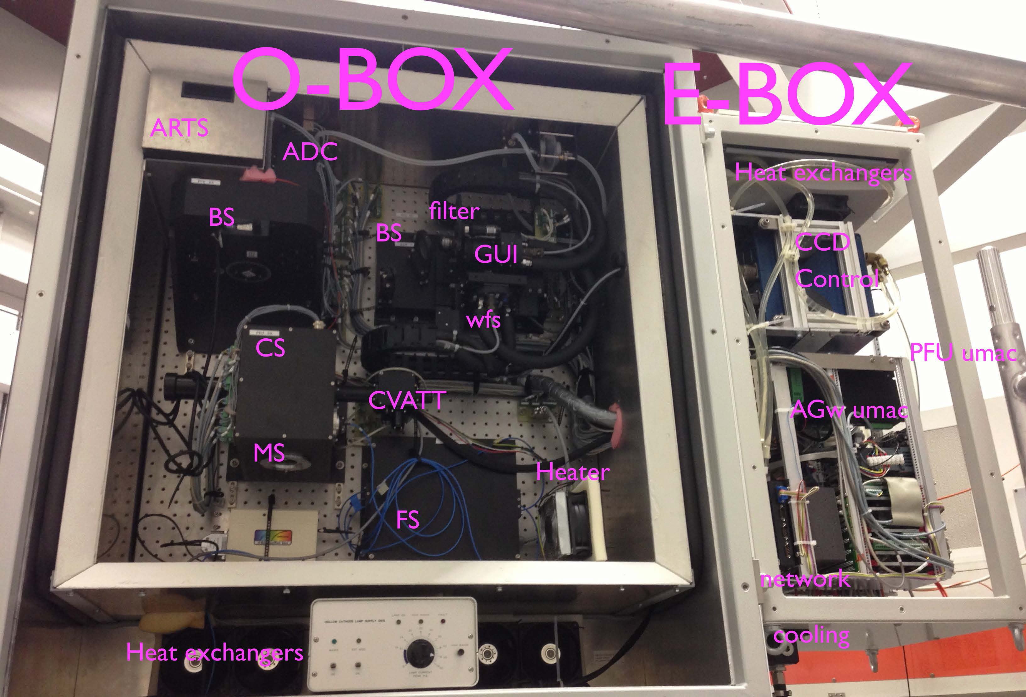
Picture of the open PFU, mounted for vibrational test at the AIP's telescope simulator. See text for abbreviations.
Credit: AIPBut the PFUs are responsible for much more than just providing permanent access to the LBT: They also house the atmospheric dispersion correctors (ADC) and the mode selector (MS) for utilizing different spectral resolutions. Different calibration light sources plus the fiber feed from the Vatican telescope and from SDI are selected for input here, too (CVATT). The artificial star unit (ARTS) is also located there, along with various beam-splitter selection wheels (BS) and a calibration stage (CS). All of the optical components are housed in the Optical box (O-Box), which has double insulation with cooling air circulation in between the isolation layers. Control electronics for PFU and AGW components reside in the Electronics box (E-Box) which has single insulation layer on the outside. The O-Box is kept at the constant temperature set at the beginning of the night to keep the optics in a stable environment. The E-Box temperature follows the ambient temperature, but is actively cooled.
Below, some CAD designs of the PFUs are shown. In the detailed drawing of the light path to the right, the light from the telescope enters the PFU at the right upper entrance. The artificial star unit follows at the upper right corner of the PFU. Just below is the dichroid beam-splitter selection wheel, which diverts parts of the light the the AGW unit left of it, but passes the 'useful' light to the science-fiber selection unit (bottom).
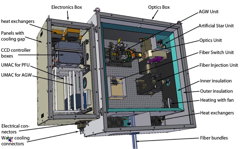
Design drawing of the PFU. Most of the parts are labeled accordingly.
Credit: AIP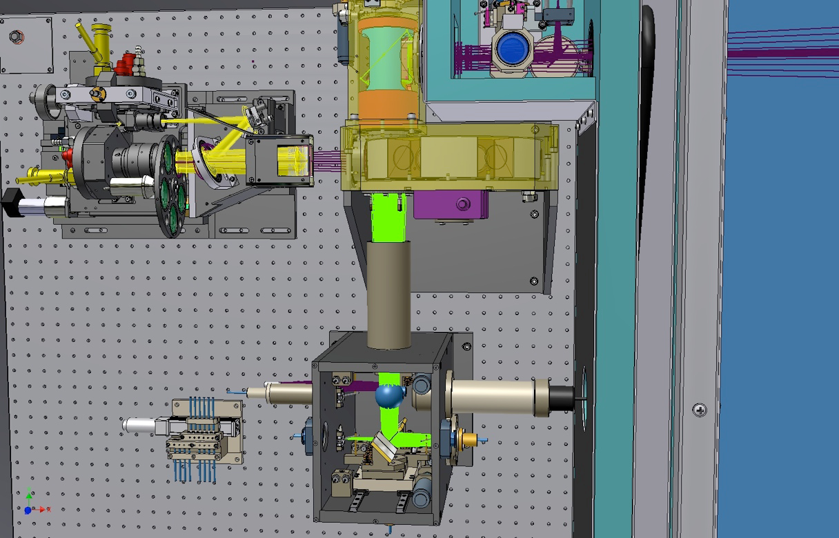
A detailed drawing of the light path.
Credit: AIPAll of the components are steered with low-level RPC servers, which in turn are operated at the user's side with several GUIs. A snapshot during real operations is presented in the picture below. During testing, the artificial star light unit was heavily used to establish proper coordinate transformations between the two images, to study the stability of the guiding process, and to tune the performance of the back-reflected pinhole image position correction algorithm.
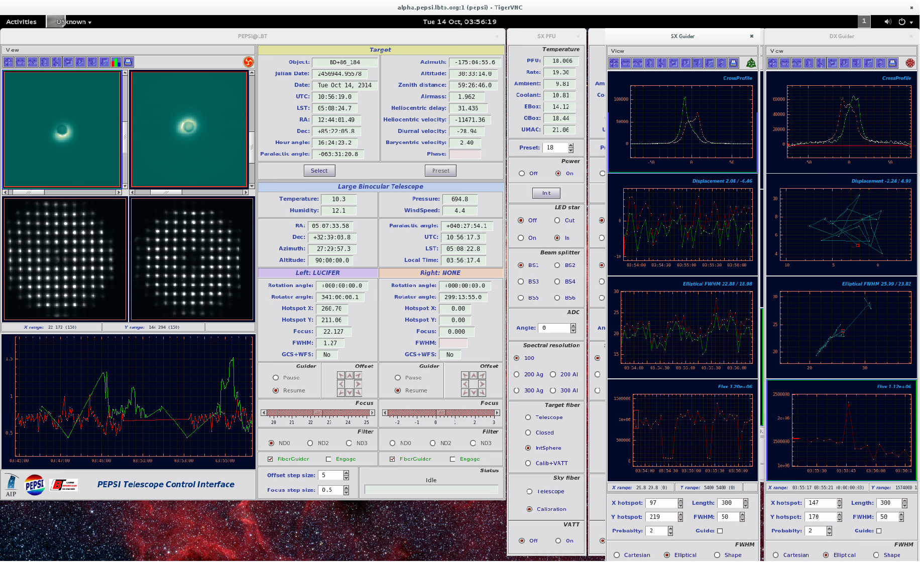
A screenshot of the various GUIS to control the PFU components: The left panel shows the back-reflected light of the guide star around the pinhole position, followed by an image of the wavefront sensing unit below. The central panel allows telescope pointing direction selection and provides guiding statistical information. The half-hidden panel allows direct control of the PFU devices, while the rightmost image shows important guiding information.
Credit: AIP